Keywords: direct current (DC), rectifier device, manufacturing equipment, industrial enterprise, Arctic.
Introduction. Energy efficiency of an industrial plant as a whole and individual technological processes in particular is one of the most important indicators of how well both that facility and the whole industry perform and how competitive they are.
We are currently witnessing an unprecedented growth of industrial activities in the Arctic regions of Russia that has not been seen in the last couple of decades. It is mainly due to the efforts to achieve targets set by the country’s policy-makers in developing the Northern Sea Route and significantly increasing its traffic volume, and on the other hand it is facilitated by increased oil and gas production in that region. Over 20% of products of extractive industries are now produced in the Arctic. Besides, the region’s share in processing industries is around 2%.
The biggest producer is the Yamalo-Nenets Autonomous District followed by the northern parts of the Krasnoyarsk Krai and Nenets Autonomous District that account for around 10%.
Arctic facilities of the republic of Sakha (Yakutia) produce almost 2% of industrial output. Western part of the Russian Arctic is where exploration started long ago with industrialisation at the beginning of the 20th century. The most diversified is the Murmansk Region with its mining, metallurgy and power industries.
Key Arctic facilities are:
✔ Kola Mining and Metallurgical Co (Nornickel),
✔ Kandalaksha Aluminium Smelter (UC RUSAL Plc),
✔ Olenegorsk Mining and Processing Plant,
✔ Kovdor Mining and Processing Plant,
✔ Kovdorslyuda,
✔ Apatit Plc, etc.
Main products are non-ferrous metals, construction materials, phlogopite, aluminium, apatite-nepheline ores, vermiculite, complex iron ores, strontium ferrite powders, aegirine concentrate, sphene concentrate, titanium-magnetite concentrate, iron ore concentrate, apatite, baddeleyite and other concentrates.
Largest infrastructure plants are:
✔ Kola Nuclear Power Plant,
✔ Hydroelectric plants of the Murmansk Region, etc.
The quantity and mix of the equipment and plant used in the northern regions are constantly growing. However, a lack of efficient and uninterrupted power supply to the Arctic does not let the production and processing of natural resources to perform at full capacity. Regional facilities have to use imported organic fuel; as a result, considerable logistical costs and poor reliability of generation equipment at the end of its lifespan lead to a significant increase of expenses and decrease of economic performance. Natural and climatic conditions of such regions limit where renewable power plants can be built to generate solar, wind or tidal energy [1]. Therefore, it is so relevant for industrial plants in the northern regions to use energy efficiently and incorporate energy efficient technologies.
Production and manufacturing nowadays are characterised by the use of all kinds of automated machinery and equipment.
A significant portion of that equipment was designed to be DC-powered. It includes machinery for electroplating, arc welding, electrothermal treatment, coating, etc. To operate from an AC circuit, such equipment comes equipped with special rectifiers.
A rectifier is a static device that transforms AC power input into DC power output. Power u1(t) is mainly supplied by a single-phase or three-phase alternating-current 50Hz network. A rectifier converts alternating AC voltage of the power source u1(t) into constant DC voltage u0(t) that apart from a useful output, constant DC component U0, has also an AC content called ripple voltage un(t) = u0(t) —U0. Acceptable ripple voltage at the output of a rectifier and its measurement criteria (parameters) are determined by specifications of the manufacturing equipment.
Rectifiers can be made as traditional or double-conversion circuits. Such rectifiers consist of a low-frequency power transformer Т operating on 50Hz frequency (D) of a power source, a bridge B and a ripple filter RF.
A transformer converts the input mains voltage (power source) u1(t) up to a level u2(t) that would ensure a required DC content of the output voltage U0is provided. Besides, a transformer provides galvanic isolation of the rectifier output from the mains that makes it possible to ground one of the output terminals of the rectifier. A bridge converts alternating AC voltage u2(t) into constant (unidirectional) DC voltage u01(t). A simple bridge is built out of uncontrolled diodes that are arranged in a specific rectifying configuration. Conventional regulator rectifiers can have a bridge made up of semi-controlled devices, thyristors, only or combine both diodes and thyristors. Rectifiers with thyristor-only bridge are often called controlled rectifiers. Almost in any rectifier circuit used to supply power to telecommunication devices, a bridge is followed by a smoothing ripple filter that is a low-pass filter. A ripple filter serves to reduce ripple level at the rectifier output to the level acceptable for the intended use [3].
Another part of the manufacturing equipment used at plants, though designed to operate from the AC mains, also contains a rectifier in its electric circuit. It primarily includes state-of-the-art metal-cutting machines and systems.
Technological processes carried out on such equipment are characterised by alternating loads applied to its electric circuits as a whole and rectifiers in particular. Such operational modes can change energy efficiency and ripple factor of rectifiers.
Keeping all that in mind, automation tools must be used to adjust the operation of rectifiers based on a load applied to them.
Purpose of this research is to establish whether high-power rectifiers in industrial equipment need to be automated and adjusted in order to increase their energy efficiency under alternating loads.
Findings of the research. As can be seen on Fig. 1, high-power rectifiers form an integral part of a technological process; therefore, their energy efficiency and how it affects power consumption of various technological processes in mechanical engineering, based on changing power levels, require additional research.
In relation to the above we should add that while there were not many variable frequency drives (VFD) used in mechanical engineering, their share in the power consumption of a plant was insignificant. However, now, with a sharp increase in the number of VFD used, their contribution, and that of VFD rectifiers, in reducing power consumption is growing [2].
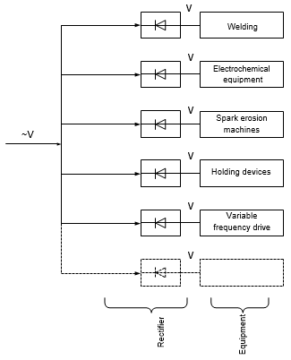
Fig.1. Examples of how rectifiers are used in manufacturing
High-power rectifiers come in two types, linear regulated power supplies and switching or switch-mode power supplies (SMPS). They use fundamentally different methods of regulating output voltage. Refer to Fig. 2 for a simplified diagram of a linear regulated power supply.

Fig. 2. Simplified configuration of a linear converter
This power supply uses a low-frequency (50Hz or 60Hz) transformer to step down AC line voltage with frequency staying the same. The resulting voltage is then rectified and smoothed. It is regulated by a positive resistance ballast, or variable resistance, wired in series with the load. The resistance is normally provided by a bipolar transistor or a FET that operate in their linear region. A feedback circuit compares the output voltage with the reference voltage and adjusts the resistance of the ballast in such a way as to ensure the output remains on the required voltage. This mode of operation causes a lot of power to be dissipated in the form of heat which eventually decreases efficiency. Because of low efficiency a power supply must be equipped with bulky heatsinks and cooling fans. Linear power supplies can only step down the input voltage. Difference between input and output voltage equals the voltage drop on transistors Udrop. Hence power dissipation on the regulator side is Udrop multiplied by Iload where Iload is the output current or load current. As the input current equals Iload, the efficiency of such converter is Uout/Uin. Therefore, in most cases practically the efficiency would be unacceptably low. Big weight and size, high cost and massive heatsink cause linear regulators in power supplies to be rarely used for applications over 10W. Such power supplies can be quite bulky, heavy and almost inapplicable for modern compact electronic devices.
Switching regulator does not have most of the disadvantages of a linear converter.
Switch-mode converters are characterized by the output voltage that can be either higher or lower than the input and opposite in polarity. Besides, as the input voltage is converted into pulses and is fed to a transformer using additional windings, it is possible to get more than one output voltage. The cost of each additional output is very low compared to the cost of a whole device.
Other advantages are reasonable form factor and price as well as high output power. Because pulse-mode frequency is much higher than 50Hz, switching power supplies surpass linear ones significantly (by dozens of times) and their efficiency would normally stand at 85% to 98%. On the one hand, it is modern components that we must thank for reducing losses. But on the other hand, a better result can be achieved by using certain circuit designs and configurations, that are often unconventional, and by optimising all conversion parameters as much as possible. At the same time, gradual miniaturisation of radio electronic devices with their power consumption on an increase, a bigger amount of available communication means, implementation of new energy efficient processes in production have made a compact size and efficiency nearly two key requirements for energy converters.
One of the main issues during AC-to-DC conversion is to regulate output voltage. To do that, both linear and switching power supplies are equipped with filter capacitors. In a capacitor:

To limit voltage fluctuations, it is necessary to either increase the capacitance (C) of a capacitor or reduce the time of a signal passing through a capacitor (dt). A huge plus of switching power supplies is having an option to significantly shorten dt (by increasing switching frequency) and thus reduce the size of a filter capacitor in such transformers.
Another obvious advantage of SMPS is converting power of almost any type. If the input is AC mains, AC voltage is first rectified and then filtered in a capacitor – the output is pulsating DC voltage. Next element of the SMPS is a high-frequency switch. Switching is done by using a semiconductor bipolar transistor or a MOSFET that turns ON and OFF thus generating voltage pulses that are fed to the primary winding of a power transformer.
The frequency of command pulses remains fixed in the range of 10 kHz to 500 kHz in modern converters, and their duty cycle is adjusted by a control system that regulates output parameters. This way the second winding of a transformer has a train of voltage pulses of desired amplitude and length. After that AC voltage in the form of pulses is rectified and smoothed by an output filter which can be a capacitor, a combination of inductor and capacitor, whichever is a topology. Such power conversion happens with least losses and ensures maximum energy efficiency of a power supply.
To summarise, an off-line switch-mode power supply must generally perform the following functions with high efficiency and little losses:
1. Rectification, to convert AC input to DC output.
2. Input filtering, to smooth pulsating DC.
3. Transformer and galvanic isolation, to provide output voltage of desired level while isolating it from the AC input.
4. Regulation, to maintain steady output voltage irrespective of changes in the mains, load and temperature.
5. Output rectification and filtering, to convert AC voltage at the output of a transformer into a series of unipolar pulses and isolate their constant component.
6. Surge protection, to protect equipment from voltage spikes at the output and to cut off in case of power interruption, overload or short circuit.
Output voltage is regulated by changing duty cycle of pulses at the switch output that causes the constant component of voltage on the load to be adjusted accordingly.
Nowadays, there exist a lot of SMPS topologies, each with their own advantages and disadvantages and each serving a certain purpose and application [2,3].
There are three basic types of non-isolated switching power supplies that are well known and have a lot of information about them – buck, boost and inverting converters. Power conversion in these topologies uses inductors and capacitors. They are simplest devices with lowest component count. Such topologies can be used to understand mechanisms of operation and methods of analysis of more complex types of converters [4].
Refer to Fig 3 for a schematic of a buck switching power supply.
To simplify the analysis of this topology and other basic topologies, we will make some assumptions. We assume that all components are ideal. A capacitor has infinite capacitance which is why we can disregard output current ripple.
This topology, like all switching power supplies we will cover later, has two modes of operation. The first one’s switching period can be divided into two states:
1. Pulse (transistor is open, diode is closed).
2. Pause (transistor is closed, diode is open).
This mode is called a continuous mode, because the current through the inductor never falls to zero.
In the other mode, the current is discontinuous, and it has three states:
1. Pulse (transistor is open, diode is closed).
2. Pause (transistor is closed, diode is open).
3. Cut-off (both switches are closed).
Discontinuous mode is a preferred option. It helps reduce the size of an inductor and a capacitor. Switches are also under lower current loads. A transistor generates a pulsating voltage that is later smoothed by a filter.
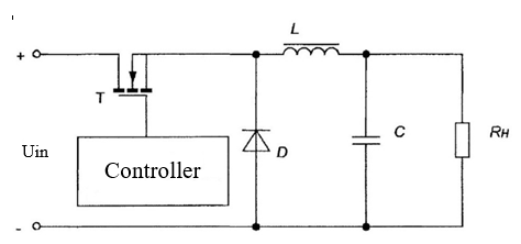
Fig. 3. Circuit configuration of a buck switching converter
With a switch open, magnetic field energy is being stored in the inductor and input voltage is fed to the output of the converter through inductor (L). When the transistor closes, the inductor current changes polarity causing the diode to open and stored magnetic field energy to be supplied to the load.
Let us calculate parameters of output voltage for this converter; to do it, we introduce , which is called duty cycle that characterises the control signal.
We will apply Kirchhoff's voltage law which is his 2nd law. Here is a circuit we are going to evaluate: Uin, T, L, Rh.

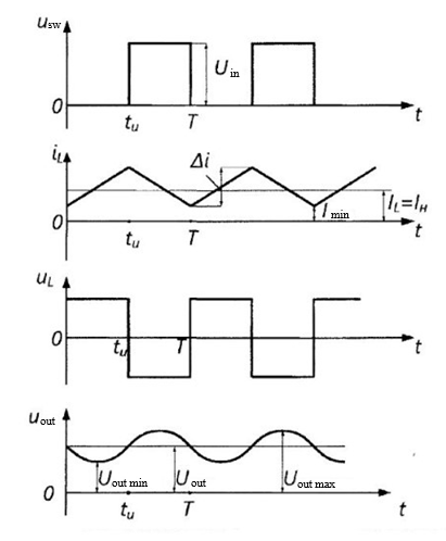
Fig. 4. Waveforms of operating buck converter
We will define voltage across the transistor as medium by using a waveform usw (Fig. 4):

with the result

Therefore, the output voltage of a buck converter is always lower than the input because D will never reach one. Output voltage is regulated by changing the D.
A non-isolated boost converter differs from a buck converter only in how the elements are connected. If the transistor is closed, the diode D is reversed biased and the input voltage Uin is only connected to L. Inductor current increases to the maximum either from a zero or from a specific starting value in the continuous mode. When the transistor is open, L voltage changes
polarity causing voltage across diode to become higher than the input voltage. The diode feeds the inductor energy and the input power to the filtering capacitor and the load. This way output voltage Uout is always higher than the input Uin. The regulated output voltage in the boost converter is calculated in a similar way as follows:

As before, in an ideal case scenario the output voltage depends only on the input voltage and duty cycle. Therefore, output voltage can be regulated by adjusting switching action [5].
Waveforms of a boost converter are shown in Fig. 5.
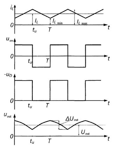
Fig. 5. Waveforms of a boost switching converter
The current fed to the output filtering capacitor is noticeably the current of the diode that will always be discontinuous. It means that the output capacitor must have high capacitance with low equivalent series resistance in order to achieve an acceptable level of output ripple. This is what makes criteria for the output capacitor of a boost converter different from those of a buck converter described above. On the other hand, the input current would normally be a discontinuous inductor current that ensures low input ripple.
Third type of the non-isolated converter is an inverting or flyback converter that can be made up of the same components as the other two. Its circuit configuration is shown in Fig. 6.
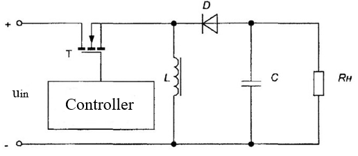
Fig. 6. Circuit configuration of a flyback switching converter
If the resistor is closed, the diode is reverse biased, and the input is connected through the inductor with stored energy as have been described earlier. When turned off, the inductor voltage reverses, and the stored energy is fed to the capacitor and the load via the open diode.
This converter is characterised by the output voltage being of opposite polarity to the input. The analysis shows that the regulated output of an inverting converter looks like this:

Based on the duty cycle D, the output voltage amplitude can be either smaller or bigger than the input amplitude. Because of that, such converters can be used in a wide range of applications, for example as a preregulator in double-conversion systems.
It is hard to achieve low ripple when using this converter. Normally it would be solved by a very big output capacitor filter.
Besides, a transistor must work with high currents as well as high voltages. Transistor in an inverting regulator is subjected to heavy loads. A rectifier diode also suffers from high current ripple which leads to increased dynamic losses.
The non-isolated converters we have covered above are limited in where they can be used. Isolation is required almost for any power supply connected to an industrial AC network. Without it, power supplies become unsafe, because irrespective of the low and safe output voltage, potential difference between outside terminals and ground can be very big. Besides, without a transformer, the described converters cannot provide the output voltage that would significantly differ from the input. Therefore, isolated switching power supplies that we are going to talk about below have a wider range of applications.
A high-frequency transformer connected between the input and output of a converter helps overcome most of the above mentioned limitations and has the following advantages:
— Galvanic isolation of the input and output to ensure that the outputs are safe when the input is 220/380 V mains.
— Transformer ratio can be varied to adjust a required output voltage that would be very different from the input.
— Duty cycle can be optimised and peak currents minimised if the transformer ratio is set correctly.
— Number of outputs can be easily increased by adding secondary windings to a
transformer. At the same time, output voltages can be of different polarity based on the polarity of secondary windings against primary one.
Such isolated converters have their drawbacks that are mainly associated with a transformer. For example, leakage inductance in a transformer in most circuits leads to voltage spikes when a power switch is being turned on. At the same time, some problems are caused by magnetising inductance that is saturated in case of overcurrent and this can lead to converter failure. It means that the magnetising current must be controlled while a transformer must be undergoing cycles of demagnetisation or remagnetisation.
Based on the mode of operation of a transformer, converters are divided into single-cycle and push-pull converters.
In single-cycle converters, the operating point of magnetisation of a transformer core is always in the same quadrant, i.e. magnetic flux density and magnetic field intensity do not change polarity, and only half of the magnetic flux is used. Single-cycle converters come in two types, flyback and forward converters. Flyback converters transfer energy to the load during the switch ON times. This way, the power cannot be transformed directly from the primary to the load but rather must be stored in reactive elements of the circuit (as a rule, transformer). Forward converters are more efficient in using materials of the magnetic core as they can feed most of the energy from the primary directly to the load.
Normally, push-pull converters have an even number of transistor switches. They have an advantage against single-cycle converters in that each cycle changes polarity of the voltage injected in the primary. This causes a transformer to be remagnetised. This makes push-pull converters more efficient in using magnetic material that single-cycle. Due to that, push-pull converters in general have better power-to-weight ratio and are widely used in SMPS of medium and high power.
We would like to point out that such SMPS must be designed for operation from the industrial AC network. Therefore, our further research will focus on isolated converters [7, 8].
Let us have a look at the operation and features of rectifiers in the manufacturing equipment.
As we have already mentioned, in the production it is most efficient to use a symmetric half-wave power switching converter as a rectifier.
Energy efficiency of such switching converter is determined by how efficiently AC power is converted into DC power for the load and how big power losses are. In a typical switching converter, overall power losses include both conductance losses Pcond and switching losses Psw. Conductance losses (current ripple put aside) depend on overall positive resistance. In this case the efficiency of a converter is calculated with the following formula:

where UL – load voltage,
IL – load current.
Total losses with load current Il and switching frequency fs will amount to:

where Rconv — positive resistance of conversion circuit (conductors, coils, transistor channels);
Ksw1, Ksw2 — ratios based on which power switch is used.
Please note that the larger the transistor and the higher its maximum allowed values, the higher are the ksw ratios.
Practically, when switches operate in parallel in an alternating mode, the efficiency of a
converter increases at full load, because Rcond decreases. At the same time, with lower loads, Psw losses prevail. Energy efficiency of a converter at every point in time, under various loads, can be determined by dependence of energy efficiency from real load.
If a device is operated under low loads, the energy efficiency of a converter significantly drops [10,12].
The research showed that a switching converter has high energy characteristics with the load being in the range of 50% to 90% of the rated value. With the load being increased to 100%, energy characteristics are reduced insignificantly while with the load dropping to 20 %, the energy efficiency of a rectifier drops significantly. If the device operates under load of less than 20%, energy efficiency drops even more, output voltage ripple spikes and the stability of operation is affected. Moreover, under low loads, more heat is generated, and power components of a rectifier become overstressed which exponentially shortens the lifespan of those components and the device as a whole. It all happens because the device starts working in the breaking-current mode.
Output DC voltage is a pulsating voltage that was smoothed by an LC-filter. With low consumption currents, the current through the inductor L becomes breaking current. Once the current breaks, key elements of the device are subjected to a much bigger load; it causes dysfunction of the feedback loop whose role is to regulate the output voltage. Therefore, if a power switching rectifier operates at less than 10% load, it is operating in its failure mode.
Thus, the use of half-wave power switching rectifiers in electrotechnical systems of manufacturing equipment leads to additional losses during conversion of AC voltage into DC output (∆P) which is due to low energy efficiency of the rectifier operating under low loads.
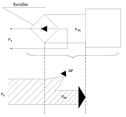
Fig. 7. Electrotechnical system of production equipment with a dedicated power rectifier,
where Pa – apparent power,
Pets – power consumption of the electrotechnical system,
∆Р – AC-to-DC conversion losses
To investigate how energy efficiency of existing power rectifiers is affected by the current load, we have conducted a series of experiments. For this purpose. we have assembled a special workbench that simulated an adjustable load with program control.
Adjustable-load workbench is built with one feature of a MOSFET transistor in mind, to limit the current passing through a circuit according to the voltage across the gate.
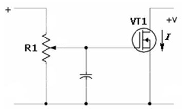
Fig. 8. Circuit diagram of a workbench to test characteristics of switching power rectifiers.
For the purpose of testing the characteristics of a power rectifier, we have taken a standard 2,000W switch-mode converter (power supply).
During our experiment, we were changing the load on the device from 50W to the maximum power with 200W step. For each step, we measured the power consumed by the device from the mains. Energy efficiency was calculated as a ratio of DC power on the load of the rectifier, that was calculated by multiplying current by voltage, to the AC power consumed from the mains. The consumed AC power was measured with a microelectronic pulse sensor that measures the active component of the apparent power in industrial AC power networks.
You can see the results of the tests establishing how energy efficiency of switching power rectifiers is affected by the load in Fig. 9. In a nutshell, energy efficiency of such devices increases fast with the increase in the load, reaches its maximum when near rated power and then slowly decreases.
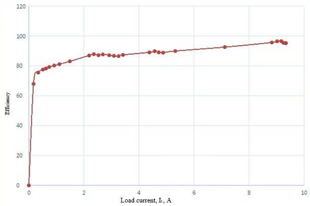
Fig. 9. Dependence of energy efficiency of a switching rectifier from the load.
Such nonlinear characteristic determines how switching rectifiers can be used in an efficient manner: specified rated power of a rectifier must be comparable to the load power. If a rectifier turns out to have too much power, a low load ends up in the region on the diagram where energy efficiency has not yet reached its maximum. Say, the load current is 0.2А – the efficiency will be only 70 % which is unacceptably low. Incorrectly selected power of the converter is one of the reasons why this can happen; another reason is the nature of loading modes of consumers.
Another important indicator of the efficient operation of a converter is stability of the output voltage. Certain experiments have been conducted on a tested half-bridge switching rectifier. The converter was loaded with an active load. When measuring how stable the output voltage is, we were varying the input AC voltage with a regulating autotransformer in the range of -20% to +15% of the rated mains voltage.
After analysing the results of conducted experiments we have concluded that stability of the output voltage in a power switching rectifier changes up to 7% in the low-load region (up to 25%) and up to 3% in the high-load region (over 90%) (Fig. 10).
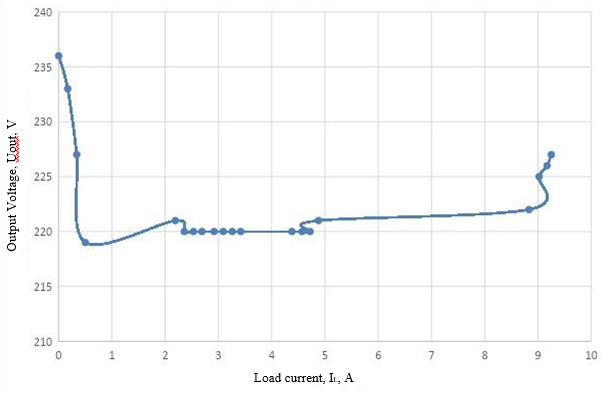
Fig. 10. Dependence of the output voltage from the load current in a high-power switch-mode rectifier.
To summarise, energy efficiency and stability of the output voltage in high-power switching rectifiers are very dependent on the load with small dependence occurring at low loads.
The use of half-wave high-power switching rectifiers in electrotechnical systems of the manufacturing equipment causes additional losses during AC-to-DC conversion (∆P) because of low energy efficiency of the rectifier when used under low loads.
Conclusion. The conducted research has shown that the use of high-power switching rectifiers in the manufacturing equipment in the low-load mode reduces their energy efficiency and affects stability of the output voltage because of operation in the breaking-current mode when internal power consumption is not sufficient. As it is deemed impossible to avoid operating rectifiers under low loads (due to how technological processes are organised in production), it is necessary to find hardware solutions to increase their energy efficiency. For example, by introducing passive loads or energy recovery devices into a rectifier circuit will help significantly improve their energy efficiency. Therefore, to optimise power consumption of industrial plants, especially in the northern regions, the production processes must be initially designed with extra capacity for future hardware optimisation of the equipment containing high-power switching rectifiers.
References:
2. V. M. Bushuev, V. A. Demyanskij, L. F. Zaharov i dr. Elektropitanie ustrojstv i sistem telekommunikacij: Uchebnoe posobie dlya vuzov / M.: Goryachaya liniya—Telekom, 2009. — 384 s.: il.
3. Hajro D.A. Avtomatizaciya i upravlenie silovymi vypryamitel'nymi ustrojstvami dlya povysheniya energoeffektivnosti pri peremennyh nagruzkah. Avtoreferat dissertacii na soiskanie uchenoj stepeni kandidata tekhnicheskih nauk // FGBOU VPO MGTU «STANKIN». Moskva, 2015.
4. Tukshaitov R.H. O koefficiente moshchnosti i Cos φ vypryamitel'nogo ustrojstva pri raznyh aktivno-emkostnyh nagruzkah i urovne emissii v elektroset' vysshih garmonik // Prakticheskaya silovaya elektronika. 2019. № 3 (75). S. 53-55.
5. Zmieva K.A., Kuznecova E.V., Ugleva E.M. Modelirovanie seti elektrosnabzheniya promyshlennogo predpriyatiya s ispol'zovaniem postoyannogo toka. // 6. 6. 6. Vestnik MGTU «STANKIN». - №4, 2014, c. 154-160.
7. Bocharov V.V., Konyahin S.F., Reznikov S.B. Dvuhurovnenvaya transportno-bortovaya sistema elektrosnabzheniya postoyannogo toka // Prakticheskaya silovaya elektronika. 2011. № 3 (43). S. 26-28.
8. Tereshin M.V., Kulagin O.A. Operativnoe regulirovanie processa rezaniya v tekhnologicheskih sistemah metalloobrabotki. // Vestnik MGTU «STANKIN», №2(25), 2013, s. 25-30
9. Zmieva K.A., Kozlov D.V., Kuznecova E.V., Dolzhikova E.YU., Tumanov D.S. Razrabotka algoritma funkcionirovaniya avtomatizirovannoj sistemy kontrolya i upravleniya potrebleniem resursov dlya administrativnyh zdanij // Vestnik MGTU «STANKIN», №2(25), 2013, S. 68-73.
10. Hajro D.A. Povyshenie energoeffektivnosti silovyh impul'snyh preobrazovatelej v rezhime malyh nagruzok // Vestnik MGTU «STANKIN». 2012. № 3. S. 83-88.
11. Zmieva K.A., Kuznecova E.V. Metodika rascheta koefficienta moshchnosti elektrodvigatelya v usloviyah nesinusoidal'nosti toka i napryazheniya // Vestnik MGTU «STANKIN», №4 (17), 2011, S. 39-42.
12. Aleksandrov D.S., Kalashnikov A.S. Strukturnyj metod rascheta tokokv zamykaniya v cepyah vypryamitel'nyh ustanovok // Vestnik Ul'yanovskogo gosudarstvennogo tekhnicheskogo universiteta. 2019. № 2 (86). S. 55-66.
13. Zmieva K.A. Modeling of an industrial enterprise power supply system using direct current // Russian Electrical Engineering. 2015. Т. 86. № 5. С. 239-245.
This in an open access article distributed under the terms of the Creative Commons Attribution License (CC-BY 4.0)

